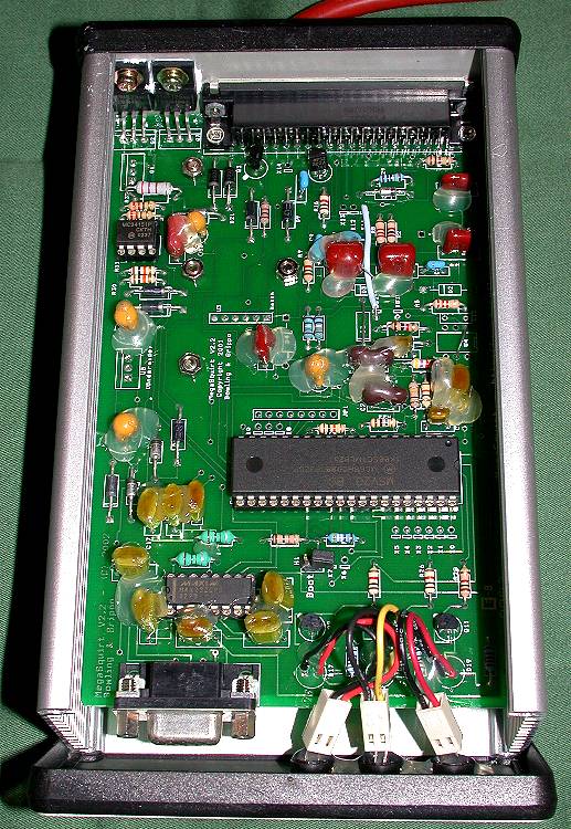
The guts.
(Click on the pictures to see a much larger version)
Converting to Megasquirt EFI in my 1973 2002
Megasquirt ECU and Related Electronics
My EFI conversion is presently based around a first-generation Megasquirt ECU using the v2.2 printed circuit board as supplied by Bowling and Grippo, but with Megasquirt 'n Spark (MSnS) firmware v3.01 to provide fully programmable ignition timing via a crankshaft reference as well. To implement the crank-trigger, I have modified the MS' tachometer input circuit to interface with a Hall-effect sensor - the original circuit is designed to connect to the points side of an ignition coil.
The guts.
(Click on the
pictures to see a much larger version)
Since I am using four low-impedence fuel injectors with a 6.8ohm resistor in-line to each, there are no modifications to the flyback circuit required and PWM current control is not used.
I am also using the Bowling and Grippo supplied Megasquirt Relay Board which simplifies installation by providing fuses and relays for the complete system including power to the fuel pump. Fuel pump power is controlled by the Megasquirt so that it will shut down after two seconds if the engine is not running.
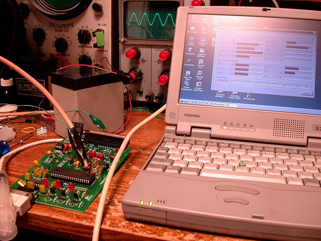
First powerup of the just-built
Megasquirt ECU,
way back in March, 2003.
The scope is showing the CPU's clock signal.
Tach
Input Circuit Modification for Hall-Effect Sensor
Ideally, the MS&S setup
wants to see a logic-level signal going "high" 10 to 90 crank degrees
before the maximum desired spark advance angle and occurring 180 crank degrees
apart on a 4 cylinder engine. For starting only, it also wants the signal to
go "low" at about 5 degrees BTDC. Using a "hardware" timing
value during cranking allows quicker starting - otherwise the computer needs
a few more sensor events to happen before it can calculate timing and begin
firing the coil. To achieve a suitable timing signal, I have a set of four magnets
(in two North/South pole pairs) on the crank
pulley.
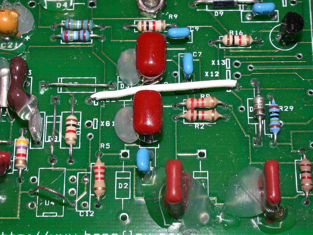
Detail of circuit modification for Hall
sensor input (click image to enlarge)
The hall effect sensor I am using to read the magnets is an Allegro UGN3177UA Hall-Effect Latch and has three pins - ground, signal, and power (4.5 to 18 VDC). The sensor output is "open collector" which essentially means the signal pin is being switched to ground. The "latching" means the signal pin is grounded in the presence of a magnetic field of a North magnetic polarity, and only opened again in the presence of a South polarity field (and vice versa).
The Megasquirt CPU's tach signal input pin is already set up for that kind of input* since the 3n25 opto-isolator output is also an open collector. To make it work with the remotely-mounted Hall sensor instead, I removed the opto-isolator and modified the board as follows: Solid wire jumpers in place of D5 and D8, resistor R10 changed to a standard 1K 1/4W unit, C12 is deleted, and U4 is removed and a solid jumper from pin 1 to pin 5 is added (the jumper in the pic was arched to give me a convenient place to clip a scope lead). If you are not worried about appearance, you could always simply connect R10 from the right pad of D8 to U4 pin 5.
With the above changes, R11 now functions as the pull-up resistor for the hall sensor output and R10 and C11 serve to filter noise and limit the current through the sensor to below the 10mA rated maximum.
*CAUTION: To go along with this mod, you will need to modify the Megasquirt Stimulator board as well by removing R9. T1 then takes the place of the Hall sensor's output transistor, grounding the Megasquirt's tach input with each simulated ignition pulse.
XG1 or XG2 are no longer necessarily used while X11 (pin 25 on DB37), normally used for the opto LED's isolated ground return, can be used with XG2 to function as the sensor's signal ground or freed up for another use. In my install, the hall sensor power is regulated 5V taken from the TPS Vref line while sensor ground is shared with the coolant temp sensor. For the Hall sensor, I used a 3-wire plus shield cable with the shield tied to chassis ground at one end only (and separate from the sensor signal ground) to avoid noise spikes being induced from the injector wiring since they run together in the engine harness.
With this circuit and sensor scheme, the tach input signal is perfectly stable and spike-free.
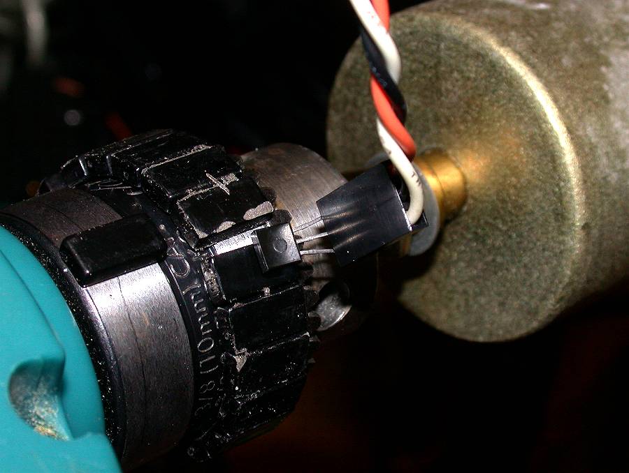
Initial testing of the Hall
sensor.
The magnets are surplus parts, originally intended for
Sonicare toothbrushes.
Injector
Ballast Resistors
The Bosch # 0 280 150 201
injectors I am using are "low impedance" units which means that current
to them has to be limited or they will overheat and/or the MS injector output
and flyback-control circuits will be damaged. Rather than use the MS' built-in
PWM current-limiting feature, I have opted for adding a 6.8ohm power resistor
in series with each injector. I did this because bench testing showed that,
when using PWM current limiting, the "stock" MS v2.2 flyback control
transistor became very hot during extended operation above 4K rpm - precisely
where I might be running on long highway trips. With resistors, there is almost
no heat buildup in the flyback circuit unit, even at 6K rpm. There is a beefed-up
flyback board and firmware available for the MS, however I wanted to avoid the
extra complexity for now.
The largest power resistors that I could find locally for a reasonable cost were only 20W and I also found that at high RPMs they can get hotter than I'm comfortable with. To keep them under their maximum safe temp at all times, they are mounted on a large, finned heatsink with plenty of heat transfer compound. The heatsink design also provides for convenient mounting and mechanical reliability. I have mounted the resistor pack outside the engine bay, in the cowl air intake for the interior heater so there will be plenty of cooling air flow. This area is somewhat exposed so the pack was made waterproof with copious non-corrosive RTV silicone. Of course, an easier, cleaner-looking alternative would have been to use an OE resistor pack from an early BMW or other vehicle with similar injectors and I may still do so if I find a suitable unit at a decent price (i.e., free).
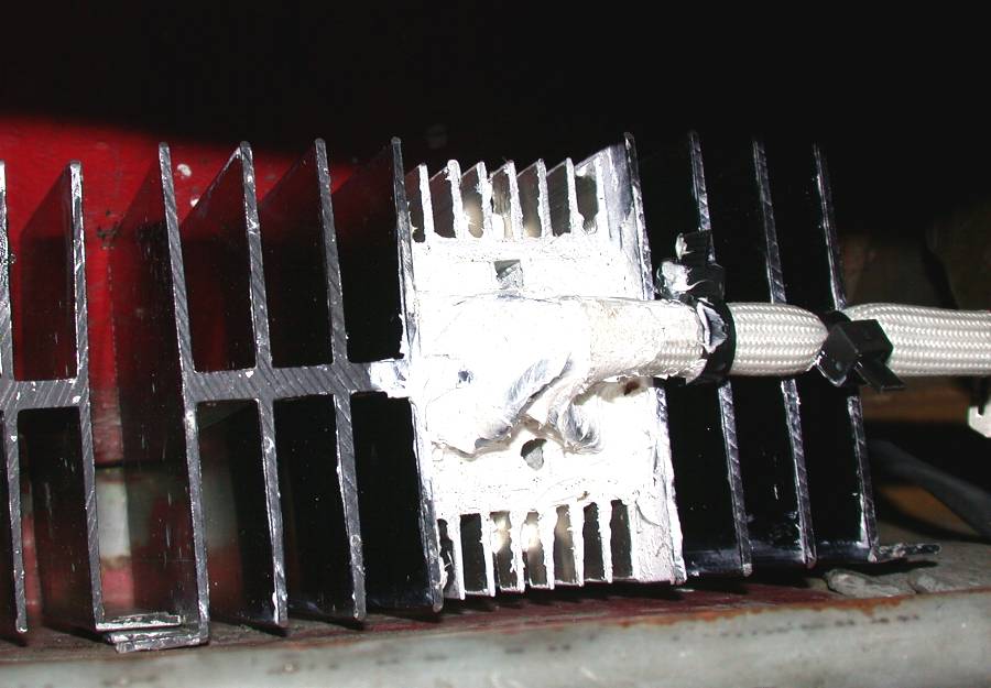
This resistor pack heatsink
is probably overkill,
but it makes me feel better
Introduction:
Why EFI?
Parts and Modifications for EFI
The Megasquirt Brain
Tuning and Driving
The Future


This
site is best viewed at 1024x768 resolution.
This web site and all images Copyright
© 2003, 2004 by Zenon Holtz, all rights reserved.