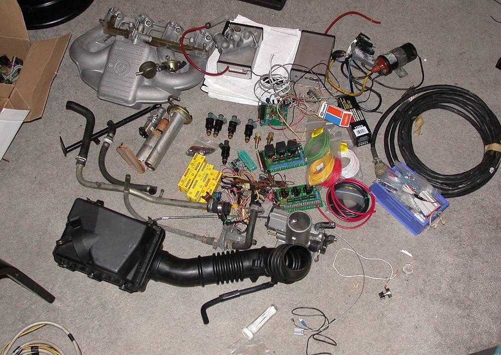
Only some of the parts collected in preparation for the conversion.
(Click on the pictures to see a much larger version)
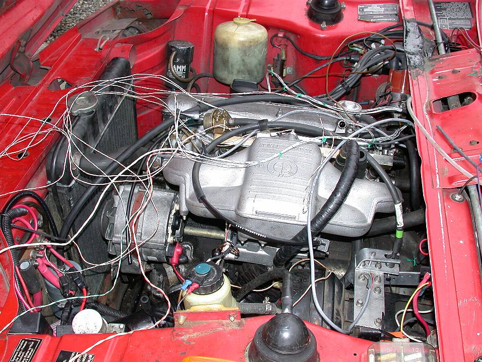
Converting to Megasquirt EFI in my 1973 2002
Parts and Modifications required for EFI
There is a long list of parts to be collected and modifications to be done in order to fit EFI to a 2002. Fortunately for us, BMW used the M10 motor into the modern EFI era and has thus provided us with all the truly hard-to-fabricate bits we need for the conversion. With any luck, most of the parts can be found very cheaply in wrecking yards or for free in your buddy's garage when he's not looking.
Only some of the parts collected in preparation for the conversion.
(Click on the pictures to see a much larger version)
What follows here is not a step by step set of instructions but more of a show-and-tell of what I did to get EFI into my particular 2002. As always, your situation will be different and you apply these ideas at your own risk.
BTW, this project has driven home the lesson that planning and preparation really pay off. Be sure to test and verify the reliable operation of everything before you install it, especially the scrounged parts. It helps with troubleshooting the installation if you can confidently rule out the components themselves. Pre-testing will also help avoid show-stoppers at install time.
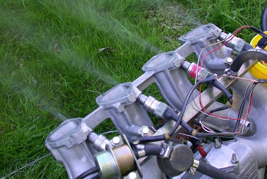
"Wet testing"
the complete EFI system before installation.
Paint thinner was used instead of gasoline
for safety. The patch of grass sprayed with the thinner
turned brown but grew back, eventually.
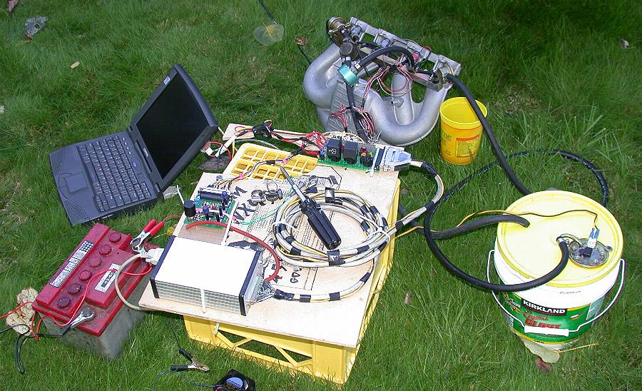
My testing setup. I am sure the
neighbors were mightily impressed.
Battery
Relocation
I had to make room for the new intake's air filter, but this is a valuable modification
in it's own right: moving ~30lbs from high in the front corner to low in the
center/rear of the car is good for handling. Also, changing the oil is made
easier and the battery should live longer since it will no longer be cooked
by engine heat.
In the 2002 world, the "standard" approach is to mount a single normal-sized battery in the trunk but for me the loss of valuable trunk space in my daily driver was not acceptable. I also had major concerns about the battery being so close to the trunk-floor fuel tank and exposed filler neck (a definite weak point in the '02's otherwise excellent packaging).
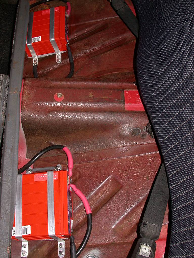
My solution was to mount two Hawker Odyssey motorcycle-sized SLA batteries under the rear seat. I used two where one might have sufficed because I really do not want any power supply deficiencies that could cause difficulties with the EFI on a cold morning.
Alternator
Compared to carburetors, EFI places much greater demands on the electrical system
- up to 15 Amps extra current draw in this case. The high-pressure injection
fuel pump is the main additional draw, plus the injectors themselves along with
the heated oxygen sensor and air-bypass valve. For this and other reasons, I
have upgraded the stock 45A
2002 alternator to an 80A alternator sourced from the same '84-'85 318i as the
intake parts. This upgrade also permitted the conversion to an electric
engine cooling fan (not strictly necessary for EFI but a very good, efficiency-improving
update nonetheless).
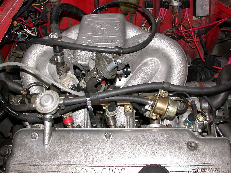
Intake
Manifold
I used the intake manifold, fuel rail, fuel pressure regulator, coolant
neck with sensors, and coolant bypass pipe from an early E30 318i. This provides
a very clean and simple"bolt on" set of EFI hardware - in many ways,
this is the easiest part of the conversion. Note that there are two similar-looking
versions of this intake - the one with injectors in the manifold and a late
E21 style with injectors in the cylinder head - make sure to get the E30 injectors-in-manifold
version and also the matching coolant manifold with sensors.
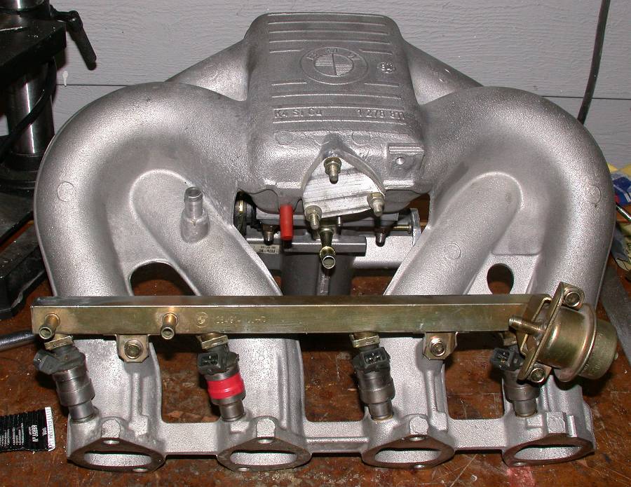
E30 318i intake manifold, fuel rail, fuel
pressure regulator, and E30 M3 injectors.
The red tape on the injector adds 20HP.
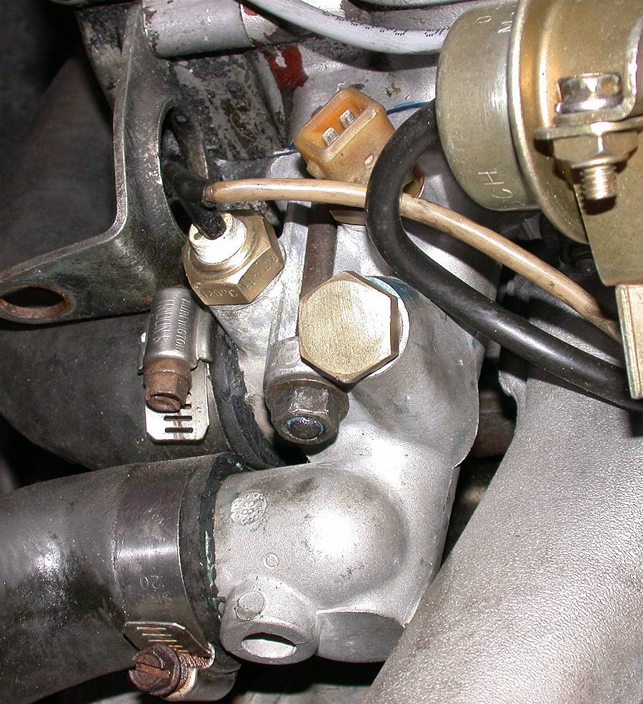
318i coolant manifold with stock 2002 temp gauge sender
(14mm thread) and 318i Bosch EFI coolant sensor (12mm thread)
for use with the MS. Note the spare 14mm sensor location
and even an extra undrilled boss for a fourth sensor.
A few adventurous souls (like Tim Skwiot) have used the tii-like early 320i intake manifold instead. While it certainly looks more "correct" under the hood, it involves too much fabrication for my tastes. Besides, BMW knew what they were doing when they changed to the later style intake - the long, 180-degree opposed intake runners of the 318i manifold really contribute to low-mid torque and the one-piece design reduces opportunities for vacuum leaks.
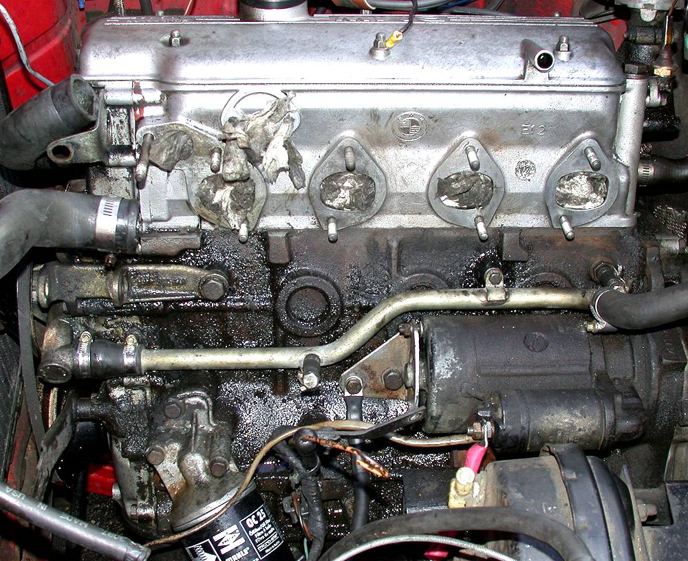
The 2002's carb manifold was heated and formed part of the heater coolant circuit so adding a coolant bypass pipe is necessary with the new intake. Fortunately, the E30 318i has one and there is even a threaded mounting boss for it on the 2002 block! The small engine block and bypass pipe outlets for the water choke/TB heat still needed to be blocked off, however.
318i bypass pipe. Be sure to get the
front rubber hose for it, too.
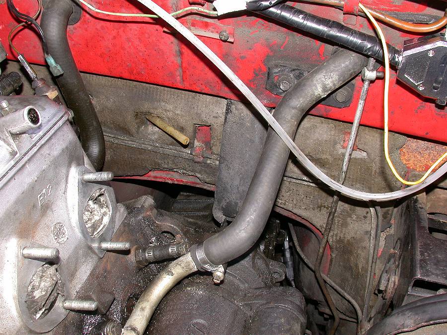
The original 2002 heater hose was shortened to work
with the 318i bypass pipe.
Throttle
Body:
The 318i throttle body
(TB) is a little smaller at 45mm than I wanted so I used a 50mm Ford unit (specific
application unknown) that also has the advantage of coming equipped with a variable
resistor type of throttle position sensor (TPS) instead of the 318i TB's switch-type
TPS. It also came with an idle control valve (to be used at a later date) and
fits a generic style of throttle cable end.
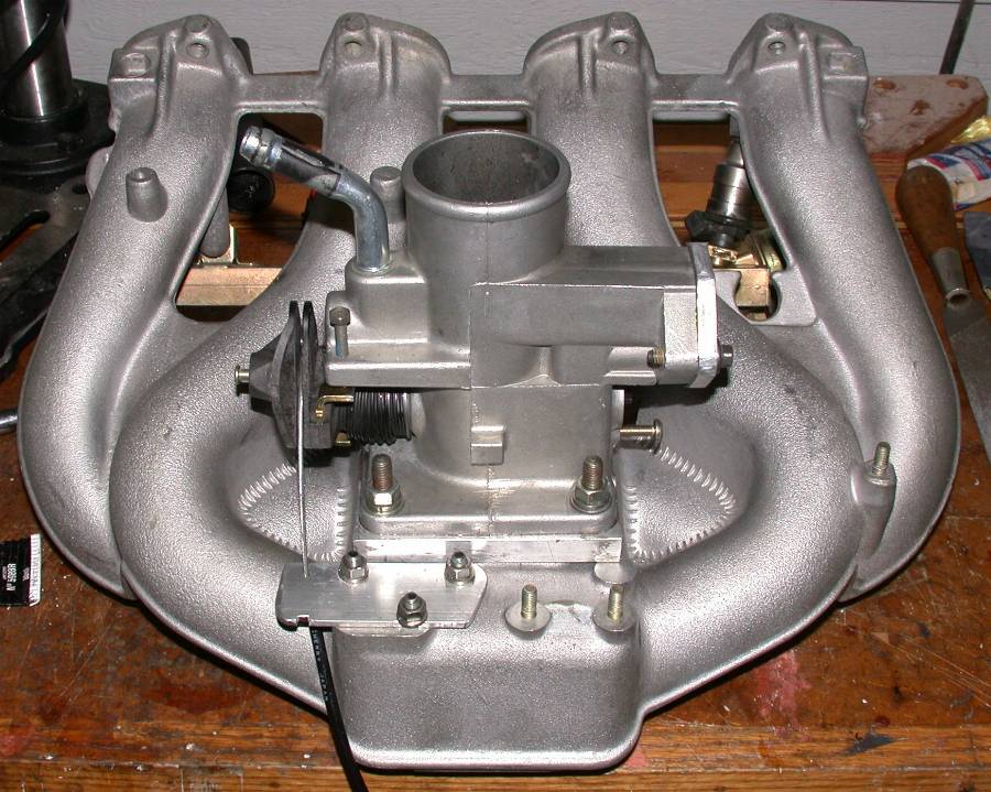
Ford TB mounted to underside of 318i manifold.
The blanking plate on the right is where the solenoid
idle stabilization valve will go one day soon. (The bike brake
cable was replaced by a proper automotive throttle
cable before system installation)
While a single 50mm throttle may sound small compared to a pair of two-barrel 40mm Weber DCOEs (for instance), consider that carbs have a much smaller choke diameter than throttle plate in order to create the venturi effect that makes them work. An injection throttle body, however, is the same size as the throttle plate (or larger) all the way through. For example, a set of DCOEs with 32mm chokes (suitable for a stock street motor like mine) has a total throat area of about 2400 sq. mm while a 50mm throttle plate has about 1960 sq. mm. But, when you factor-in the area blocked by the four throttle shafts as opposed to one, it gets much closer. For reference, a 38 DGAS has two 27mm venturis for a total area of ~1150 sq. mm and a 32/36 DGV is actually very similar area-wise, with 26/27mm venturis. You can have too much throttle area, too. A very large throttle area relative to the motor displacement can make fine power control just off idle difficult.
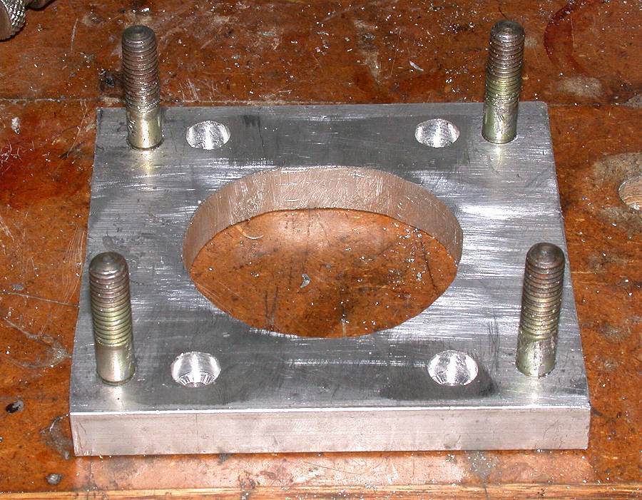
My crude TB adapter plate - no CNC milling machine here!
This was fabricated from 1/2" aluminum plate using only a small power
scroll saw and bench-top drill press. Hey, it works...
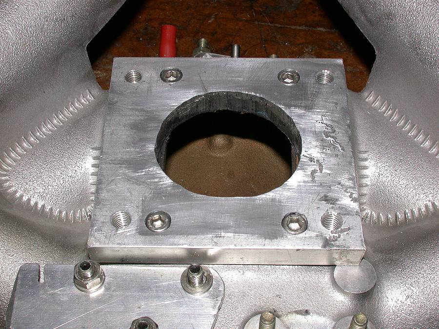
Adapter plate mounted to
manifold with flush allen-head bolts.
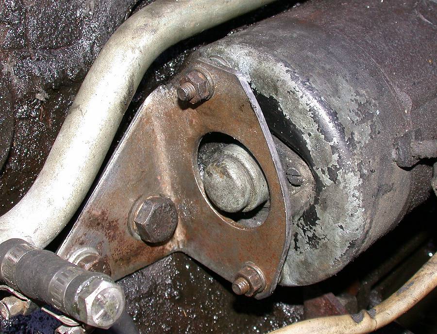
Starter
Motor Bracket
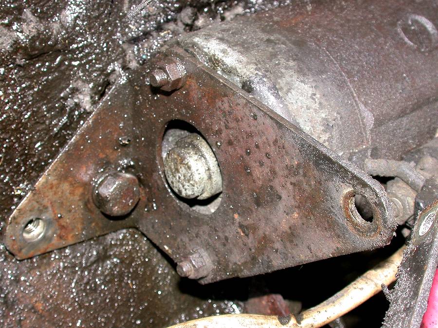
The starter support
bracket had a protrusion for supporting the carb intake manifold. It got in
the way of the big throttle body on the EFI setup and had to go.
Fuel
Injectors
The ~14 LB/hr injectors
that came with the 318i intake are on the small side for a 2L with high hopes
so I am using 23.2 LB/hr flow units originally from an E30 M3. The same injectors
are also used on some E28 5, E24 6 and E23 7-series BMWs and probably in other
makes as well. They are Bosch part# 0 280 150 201. Four of these should be adequate
for up to 190 HP, more than enough for my stock and tired motor making, at best,
120HP. They are a low-impedence injector and are being used with ballast
resistors. The fuel rail pressure is 3 Bar above manifold pressure, same
as OE.
Crank
Trigger Wheel and Sensor
Since I am using the Megasquirt & Spark firmware variant to provide
programmable control of the ignition timing as well as the fuel supply, there
needs to be a way for the MS to precisely know where the crank is in its rotation.
Naturally, the best way to do this is to read some kind of reference directly
off of the crank, thus eliminating the slop introduced by the timing chain,
distributor drive gear, and distributor shaft of the original distributor-timed
setup.
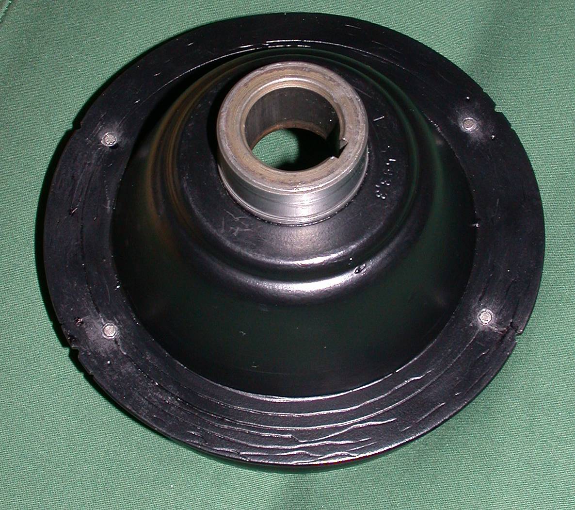
Completed trigger wheel/pulley.
To achieve a suitable timing signal, I used four magnets on the front crank pulley and a Hall-effect sensor to read them.
The back of the pulley flange was not meaty enough or at the right angle for mounting the magnets directly so I made a magnet mounting ring from 1/16" aluminum sheet. First, I lightly punched the center and scribed the circles (inner dia., magnet ring, outer dia.) then carefully drew the lines through the small centermark to get the magnet positions as accurately 180º apart as possible which is absolutely critical to smooth running. I drilled the magnet holes first, then cut the outer and finally the inner circles with a drill-press-mounted circle cutter (the crazy scratches on the ring are what happens when you forget to tighten the cutter arm). The inner circle was sized very carefully so that it would exactly match the diameter of the pulley's tapered body at the point where the ring is against the pulley flange, thus holding the ring perfectly concentric. Maintaining pulley balance is not really an issue because the ring and magnets are symmetrical and weigh almost nothing.
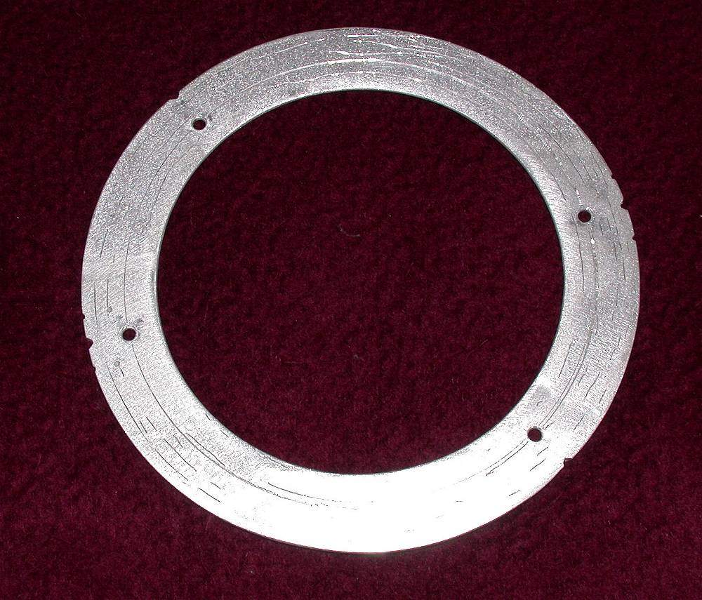
The magnet
mounting wheel.
The ring and magnets were then glued to the pulley with JB-Weld epoxy. The notches indicate the leading and trailing magnet positions to aid sensor alignment. Remember: magnet alignment on the pulley is done relative to the sensor, not the TDC mark on the pulley.
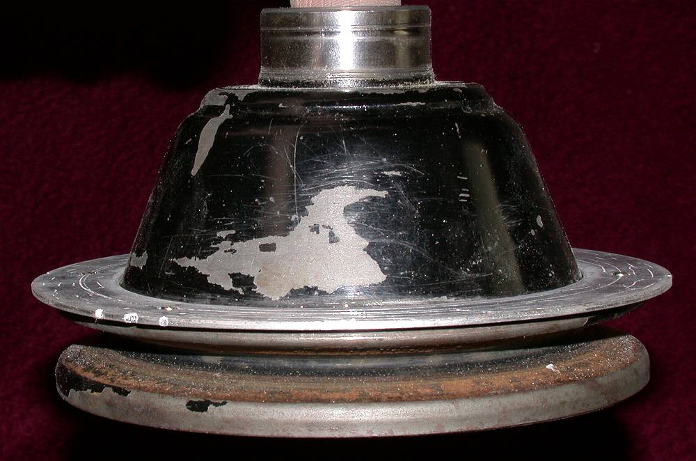
View of magnet mounting wheel on pulley.
The magnets are tiny yet powerful 1/8"x1/8" rare-earth rod magnets bought from Lee Valley Tools - 10 for under $3.
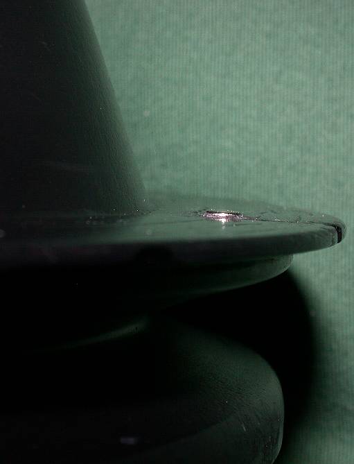
Trigger magnet sits just proud of the aluminum ring.
The Hall sensor's bracket mounts to the water pump's lower two M8 bolts. It was built extremely rigid to avoid any vibration-induced timing jitter. The oversized, slotted holes allow for sensor alignment with the magnets and a slight amount of adjustment for the cranking trigger timing. For running timing, as long as the leading magnet passes by the sensor between 5 and 90 degrees before the maximum spark advance you'll need to use, the actual magnet/sensor relationship can be adjusted-for in the software.
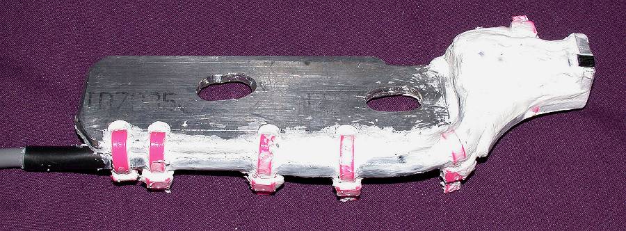
Hall sensor mount.
(The hot-pink zipties raise engine redline by 300 RPM.)
The white goop is a non-corrosive RTV silicone used to weatherproof the connections and isolate the sensor body from the aluminum mount. Hard epoxy is not recommended here since the sensor chip could be adversely affected by mechanical stresses caused by thermal expansion of the various parts. The sensor's leads are delicate so it and the cable wires were soldered to a small intermediate circuit board.
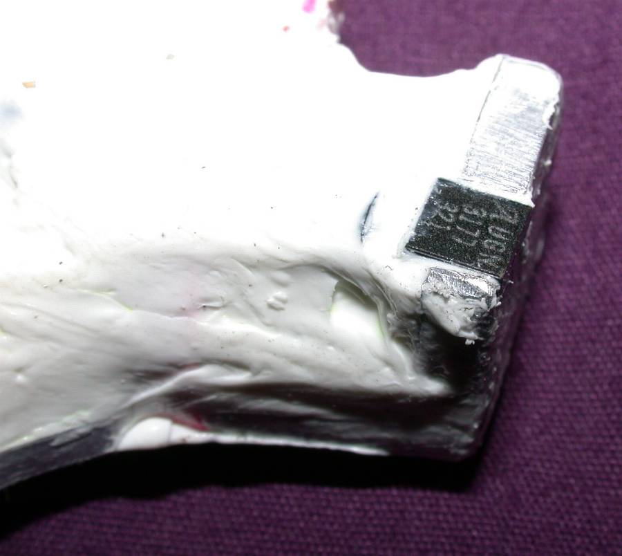
Hall sensor chip.
Here are the trigger ring and sensor in position on the engine. The gap between the sensor and magnets is approximately 1/8", which is about half of the maximum allowable distance for reliable triggering.
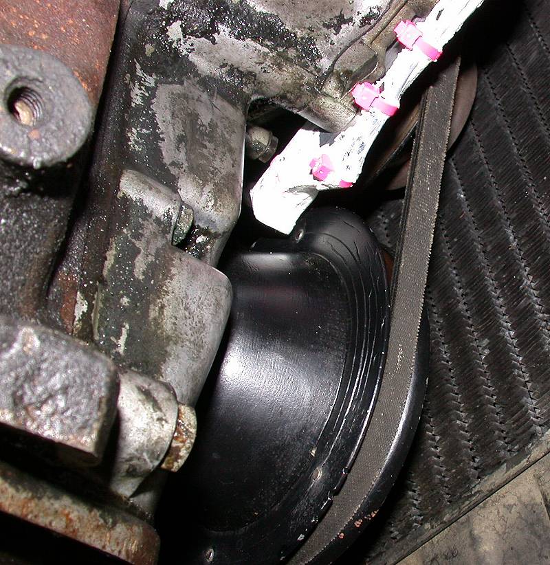
Trigger wheel and sensor arrangement.
Idle
Speed Control
One aspect of the Megasquirt that is not yet fully developed is the area of
active idle speed control. Presently there is no closed-loop idle speed control
to compensate for cold running or increased electrical loads from headlights,
an electric engine fan, heater, etc. Fortunately, control of Bosch or Ford style
2-wire idle air valves is coming soon.
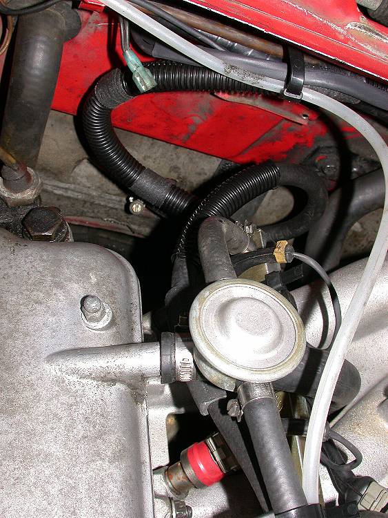
To provide good cold driveability in the mean time, I have adapted a Bosch all-mechanical thermostatic auxiliary air bypass valve. The valve is electrically heated much like an electric choke, but works in reverse - it allows more air to flow when cold. Normally, this kind of valve is mounted to the block or head so that engine heat keeps the valve closed for a hot re-start. However since the 2002 engine does not have a convenient mounting spot for the valve, I have mounted it on the intake manifold where the 318i's cold-start fuel injector used to be. The manifold remains quite cool so warm starts usually result in a high idle again. In use it has not really been a problem since the valve will close much faster than when started from cold. Regardless of idle air flow the Megasquirt ECU adjusts mixture to compensate for any engine coolant temperature and idle speed.
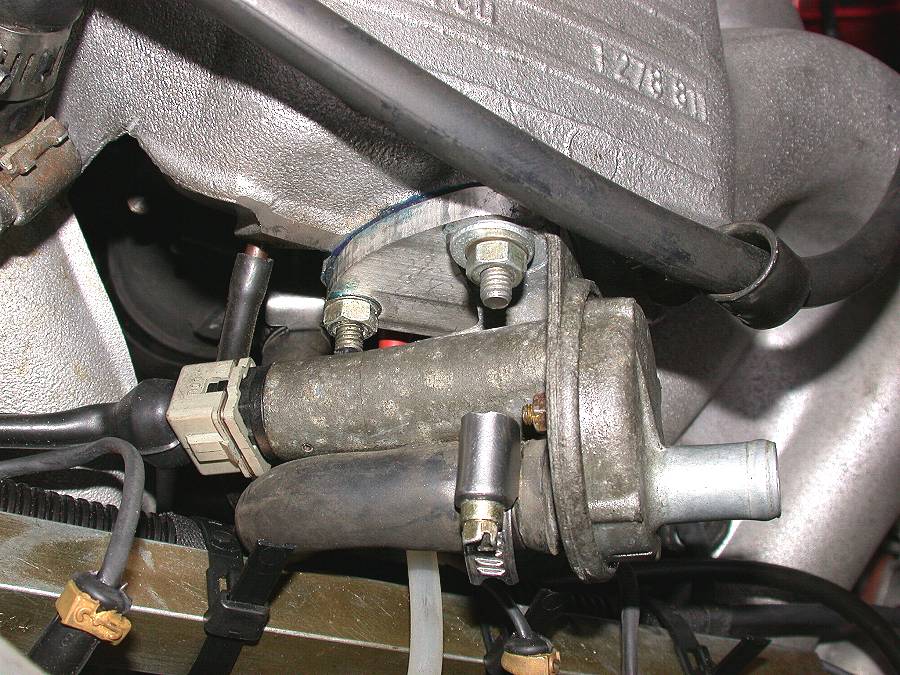
This valve is originally from a smaller motor and did not flow enough air for my engine on a dead-cold start. I was able to increase the opening a bit by moving the spring adjustment stud but still needed to file the opening in the shutter to be about 20% larger. The valve from an early BMW 320i would be ideal.
Throttle
Linkage
The stock 2002 rod-type
throttle linkage won't work with the new throttle body and so must be converted
to a cable setup. I put considerable effort into making sure the pedal action
would be smooth and progressive since driveability in bumper-to-bumper traffic
depends on fine throttle control.
At the throttle body end, all that was required was a reaction bracket to hold the cable jacket at just the right angle. This was fabricated from a steel part that came with the 318i manifold and attached via some existing fortunately-positioned studs. It has just enough springy give to prevent straining the linkage at full throttle. The throttle cable is a new "surplus" part, perhaps originally for a Chrysler product. It was found for ~$3 at Princess Auto.

The pedal side of the cable is a bit more involved... The cable could simply attach directly to the lever arm at the pedal box with a reaction bracket for the cable's housing mounted on the firewall or engine*, however, care must be taken to convert the range of motion of the accelerator pedal to match the throttle body, otherwise you could end up with more of a short-throw "on-off" switch instead of a continuously-variable throttle control. Shortened accelerator pedal travel can be fun for a little while because it initially fools you into thinking there's more power, but it gets old pretty fast in stop-and-go traffic.
*Caution: if the pedal-end cable reaction bracket is mounted to the engine there is a risk of major unintended acceleration if an engine mount ever fails and minor "control input amplification" with normal engine movement.
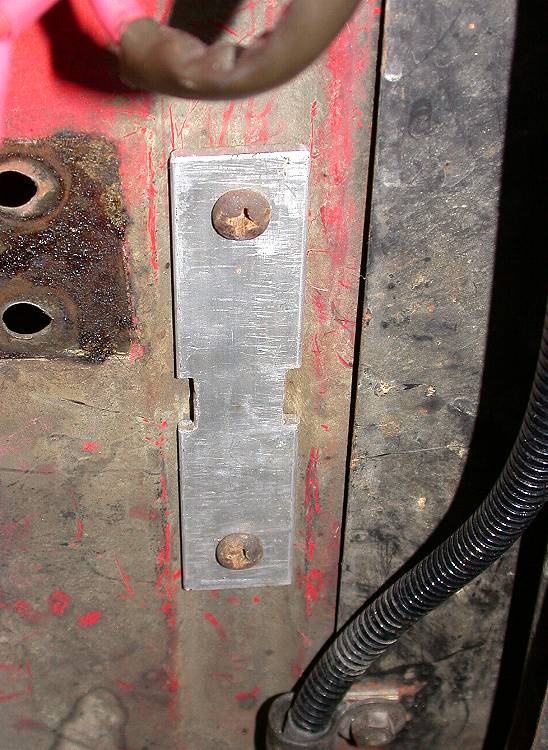
My solution (with a nod to Larry Harris' '02 EFI install, where I first saw this done) was to fabricate a rigid bracket for an intermediate lever and reaction point for the cable housing, that mounts to the top of the brake booster bracket.
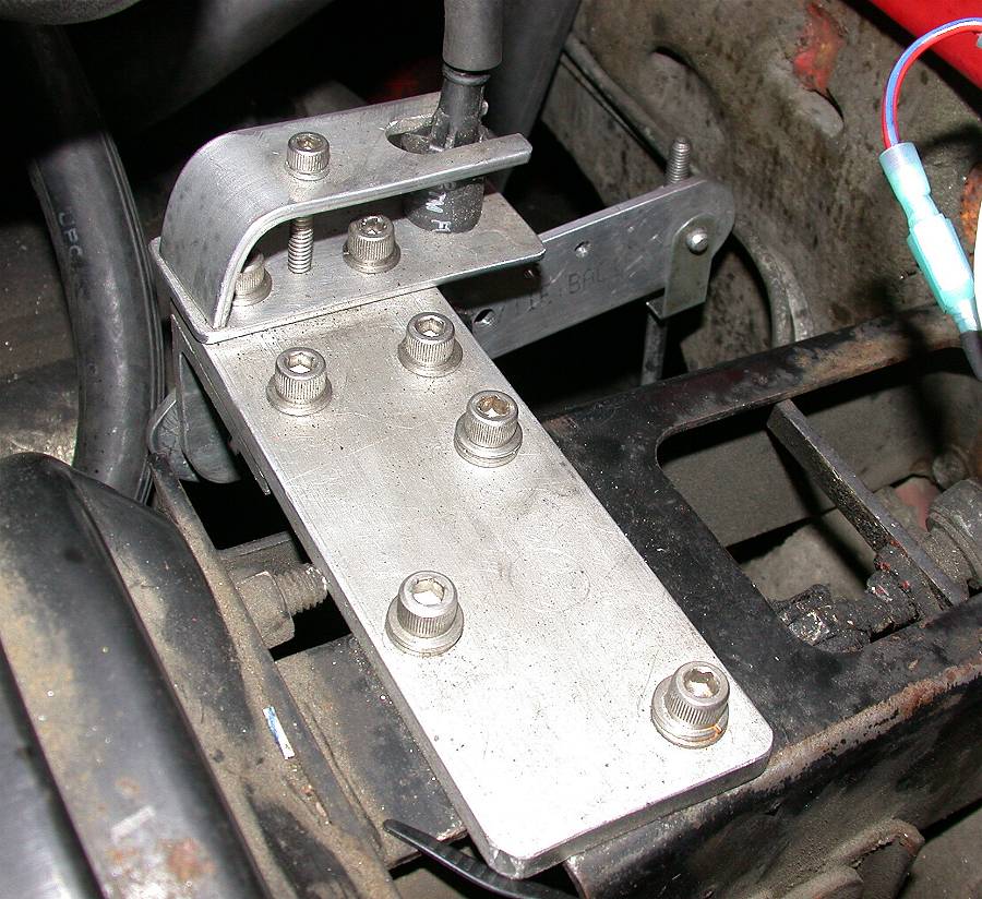
The screw holes in the booster
support were threaded for the three mounting screws
to ease removal/replacement of the bracket.
The motion range translation is done by carefully selecting where on the lever the throttle cable and pedal link rod attach. In my case, the pedal link rod's travel is ~3" while the throttle cable pull range is only ~1.25", so the link rod pulls on the end of the lever and the cable is attached closer to the lever's pivot to achieve the required 2.4:1 ratio. I did it all by direct measurement and trial and error, but trig propellerheads could have figured it out on paper.
The throttle body I am using has a strong compound return spring but, for safety, I will soon add another to pull up on the intermediate lever, similar to the '02's original main throttle return spring.
The intermediate lever is pulled downward by a shortened version of the original vertical link rod that attaches to the lever coming out of the pedal box. Note that the lower part of the rod was straightened, cut, and then re-bent so as to retain the threaded top end for the pivot/length adjuster. (It definitely helped to have a spare link rod to use as a reference.)
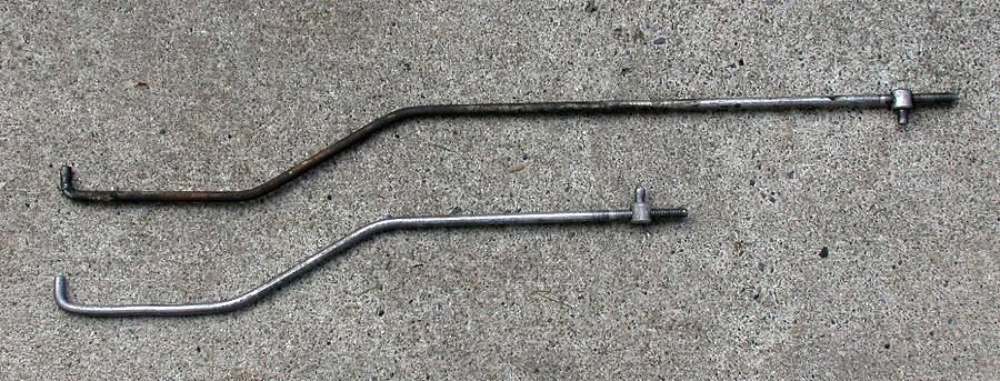
Original vs. modified link rod.
Fuel
Supply
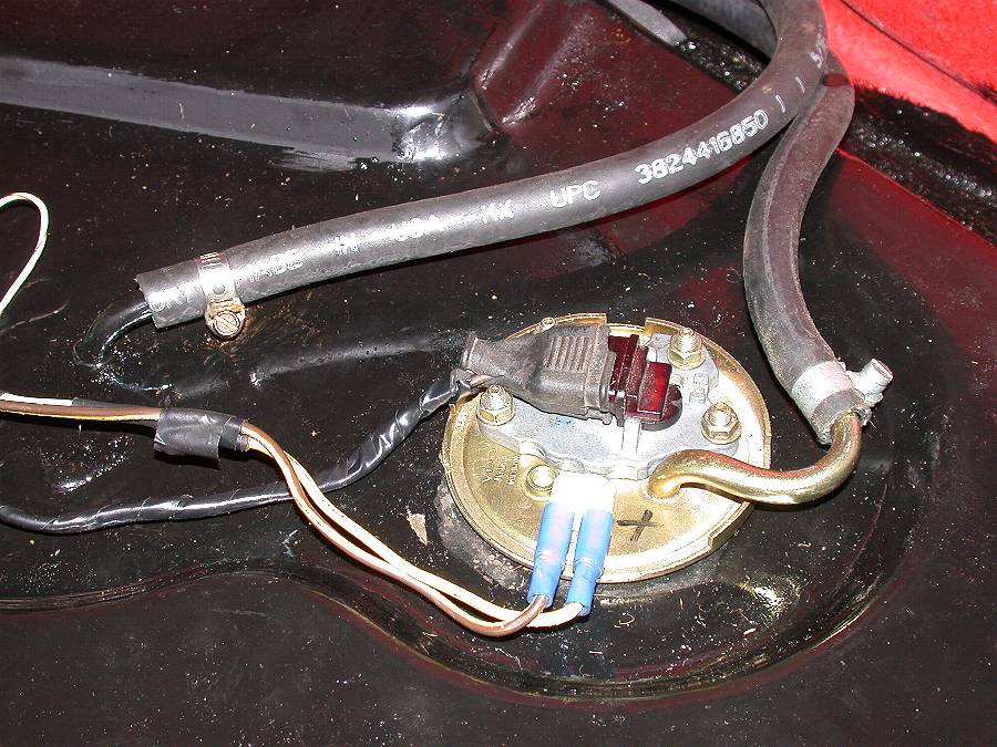
The in-tank high-pressure
fuel pump and level sender assembly from BMW '88-'91 E30 3 series models drops
right into the 2002 tank in place of the original level sender/pickup. The only
drawback here is the fact that it is slightly shorter and will thus not quite
empty the tank. The gauge will show empty relative to the new pickup's length
so there should be no surprises, though. A bonus is that the new sender includes
a contact for a low-fuel warning lamp (that I will add to the fuel gauge, one
day... I ran the extra wire for it when I ran the ones for fuel pump power).
In addition to the high-pressure pump, the EFI system requires a high-pressure-safe fuel supply line and a fuel return line. Fortunately, '73 and later carbed 2002s came with a steel fuel return line that can be used as the high-pressure feed line, while the original plastic supply line can be used as the return to the fitting on the tank. This is what the factory did for the 2002tii system and is what I have done as well (ideally, however, one would run a second steel fuel line under the car and abandon the plastic line since it runs through the passenger cabin). All rubber lines are 8mm (5/16") ID and have been replaced with 100PSI FI-rated hose.
The fuel filter is conveniently mounted on the forward bulkhead above where the supply line comes up from the frame rail, in essentially the same location as in the 2002tii. I am using the filter from a BMW E30 325e, i, etc. since it is common, relatively inexpensive, and has plain 8mm hose barbs. It is also very large and lasts a long time.
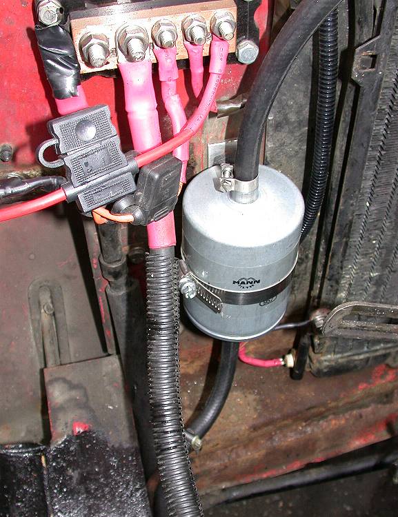
E30 fuel filter on custom bracket
Filter clamp securing bracket

High-density foam is used to protect filter
can from the screw heads and provide support
Ignition
Module
The Megasquirt drives
the ignition coil via a Bosch 7-pin Hall-effect TFI module with internal dwell
control. The specific module (Bosch # 0 227 100 103) and TFI coil I am using
came from an early 80's VW but most European makers used similar modules at
some point. This module is designed to interface with a distributor-mounted
hall sensor and is triggered when the hall sensor signal wire (in the VW harness
it is green with a white stripe) is grounded. In this installation, the MS triggers
the module instead, grounding the module's signal wire through the re-purposed
fast-idle relay output.
The TFI module has only four wires that need to be connected - iginition-switched power, coil negative, ground, and the sensor signal. The VW wiring colour scheme had coil negative as green and ignition power as black, which is exactly opposite BMW's color code so I swapped the two connector pins around to make the wire colours match my application and avoid future confusion.

The module needs to be mounted
to a heatsink,
though this one may be overkill...
Beware that there are identical-looking Bosch ignition modules out there that do not do internal dwell control (and so you can burn up your coil), and some modules that are designed to interface to a variable-reluctance sensor and may not be reliably triggered by the MS' output. In testing I noticed that the module I am using has the added feature of switching off the coil power after 3 seconds of no signal input so there is no risk of burning out the coil or module if the ignition key is left in the run position without starting the engine.
I have mounted the ignition module (and injector resistor pack) outside the engine bay in the air intake plenum for the cabin heater so there will be plenty of cooling air flow.
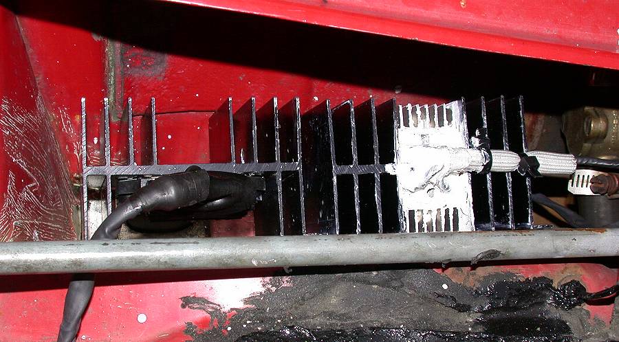
Ignition and resistor pack
heatsinks
(the black mess is part of my two year old "temporary" repair
of a previous owner's firewall hatchet work, no doubt done
so he could get the distributor out without removing the cap)
The distributor remains but is now only being used to direct the spark voltage to the correct cylinder - all timing is done based on the crank trigger and controlled by the Megasquirt. There is no need to lock the mechanical advance mechanism, though - in fact, it is better to let it operate since this distributor does not have a wide-tipped rotor like the later fixed-rotor computer-timed distributors do. The primary side of the distributor (the points/condenser or ignitor) can also be left in place as a backup for the TFI module.
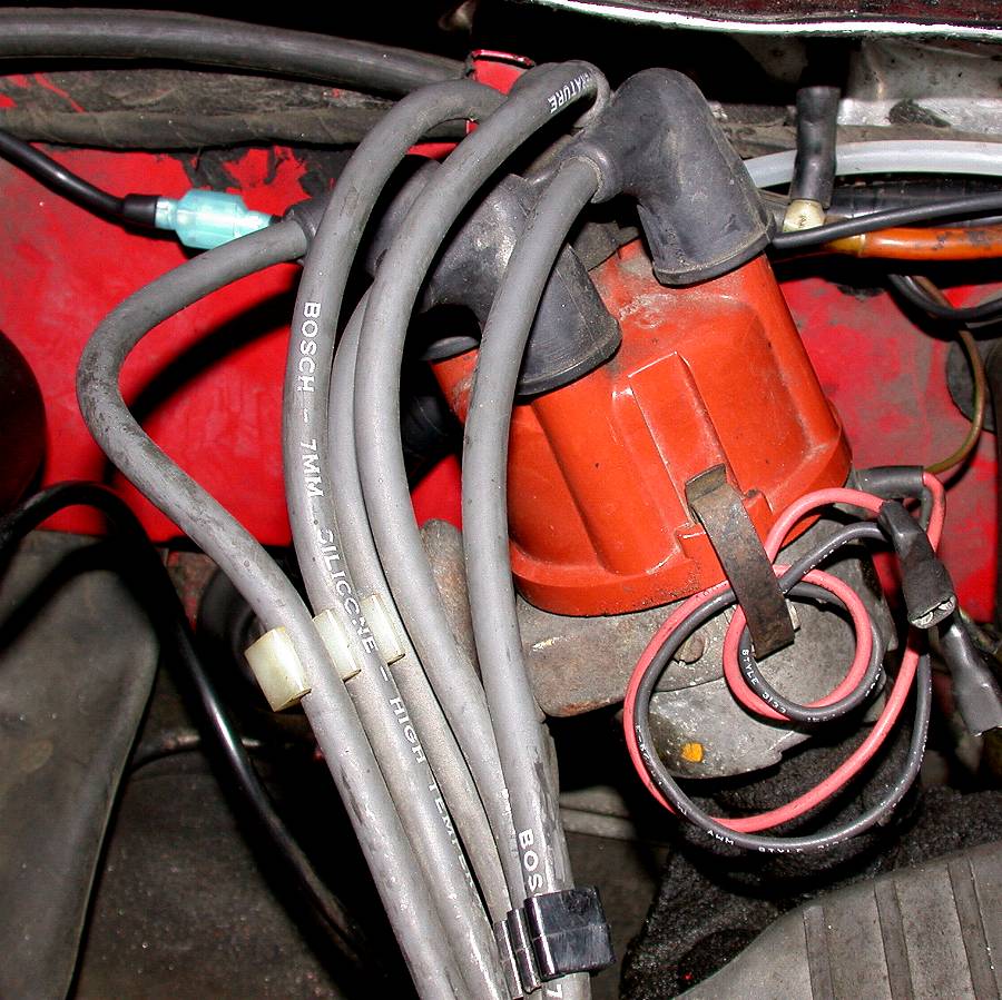
The now-unused Pertronix
Ignitor wires.
Wiring
Naturally, new wiring had
to be installed to go with the EFI - both in the engine compartment and to supply
power to the in-tank electric fuel pump. However, I did no cutting or other
irreversible modification to the original wiring harness - the EFI system's
wiring is modular and added in parallel.
Creating the engine harness was time consuming
but well worth the effort to do it properly and neatly.
A big help in this regard is the optional Megasquirt system relay board that provides fuse protection and relays for the fuel pump/o2 sensor heater along with a set of terminal strips for connections to power, injectors, and sensors. The relay board greatly simplifies installation into a carburetted car and also makes for a more easily-modified setup. Only one thick cable runs between the relay board in the engine compartment and the ECU which is mounted to the "roof" of the glove compartment where it is well protected.
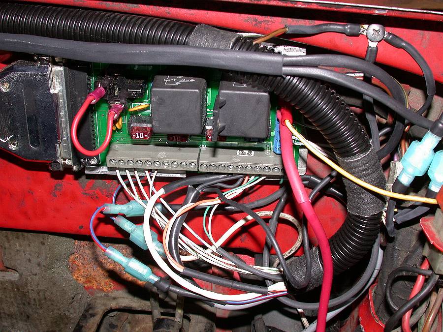
Megasquirt Relay Board mounted on the driver's side firewall,
where the emission control relays used to be.
Finished engine wiring harness
looks almost OE...
Injector and sensor connector pigtails were salvaged from a BMW 533i engine harness but installed with Teflon-jacketed multicoloured (enough to have a unique colour code for every wire in the harness) mil-spec wire salvaged from some thick marine radio system cables. Shielded cable is used for the throttle position sensor, crank trigger, and '02 sensor while twisted pair is used for the coolant and air-temp sensors. All wiring is carefully sheathed and routed to protect it from heat, chafing, and conductor fatigue. All splices are soldered and sealed with adhesive-lined heat-shrink tubing and all connectors are packed with silicone dielectric grease for corrosion protection.
Loops in the wiring harness
and
fuel lines allow for engine movement with
minimal stress to the wires and hoses.
Oxygen
Sensor
A big part of what makes the Megasquirt EFI system so easy to tune is the inclusion
of an exhaust gas oxygen sensor for feedback on mixture and for closed-loop
adaptive mixture control. While you can certainly do just fine without an o2
sensor, I did not want to miss out on the option so I added one to the '02s
exhaust system.
A threaded "bung" needs to be welded into the exhaust in a position that will allow access to the sensor for replacement but will also keep it out of harm's way. Ideally, an o2 sensor should be mounted as close to the engine as possible so it can be properly heated at all times, but also where it can sample all four cylinders' exhaust. On a stock 2002 exhaust system, that means the sensor should be right where the down-pipes merge into one. However, for clearance and ease of installation with the down-pipe still on the car I went a bit further back. Fortunately, you can use a use a self-heated three or four wire o2 sensor that will reach operating temperature quickly and stay there even at idle.
Ideally, you want the sensor head level with or lower than the sensor body so that condensation will not collect, but since in my case the sensor was installed with the exhaust still in the car and access for drilling the hole and welding the bung was limited, I settled for it being slightly above the body. As long as the exhaust is fully warmed up each time out, moisture in the sensor should not be a big problem.
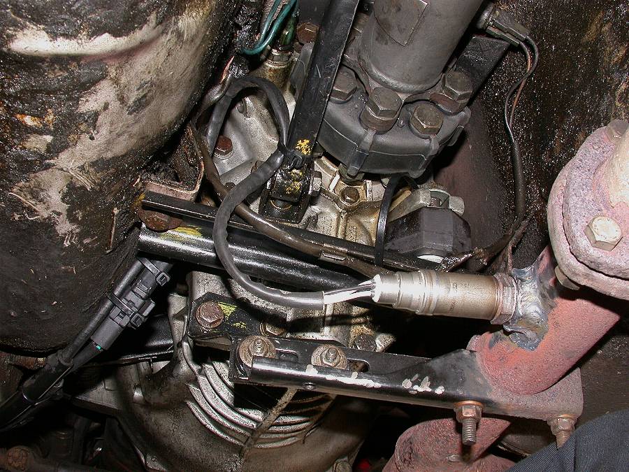
As installed, the sensor is protected somewhat from road debris by the transmission exhaust mount bracket. The sensor itself is a Bosch #13953, from a Ford application and one of the least-costly 3-wire sensors available. The matching connector pigtail is an Echlin # EC98. I ran the sensor cable up alongside the speedometer cable and well-protected inside some 3/8" fuel hose.
For the ultimate in mixture tuning feedback, I will install a wide-band sensor soon after the Megasquirt guys release their Precision Wide-Band Controller.
Air Filter
I happened to have a K&N-style
cone filter handy and so combined it with the intake tube from a Mazda MX6 and
the intake elbow from a 320i to complete the run from the filter to the throttle
body. The filter gets some cool air from behind the left headlight but ideally
there would be no exposure to engine compartment air. I'll probably install
a suitable factory-style closed airbox and filter if/when I find one. The intake
charge air temperature sensor is mounted on top of the tube and for now is the
same type as the coolant sensor which is not ideal since it is much slower to
respond than a proper open-element air-temp sensor.

Introduction:
Why EFI?
Parts and Modifications for EFI
The Megasquirt Brain
Tuning and Driving
The Future


This
site is best viewed at 1024x768 resolution.
This web site and all images Copyright
© 2003, 2004 by Zenon Holtz, all rights reserved.